Even the most cursory Google search on robotics simulation will have you come across this thing called URDF. For something that defines the very existence of a thing in simulation, the Unified Robotic Description Format (URDF), in my opinion, is very rightly named. In short, this is the file that tells your simulation software, what it is that you are simulating. It contains information about the physical bodies (links) on your robot, how these bodies are connected to each other (joints), and how these connections are actuated. All of this is written in the extremely simple XML format. A typical URDF file looks something like this.

The Gazebo and ROS wikis go into excruciating detail on how exactly to use a URDF file in simulation. However, I find that most newcomers (including myself) often get stuck one step before the actual usage. The primary question for a lot of us beginners is “how do I even convert my super complicated robot into the URDF format?”. “Do I need to manually write the whole thing??”. “Is there maybe a software tool that can get this done for me?”
And the short answer is, “there is but it may not be for you”.
If you are a Solidworks user then congratulations!! Converting your CAD model into a URDF file is super easy for you. Just move on to the next section keeping that blissful sparkle in your eyes unharmed from all of life’s challenges.
If, however, you do not have access to Solidworks, then things get a bit trickier for you. There is a really good workaround but you need to have access to MATLAB and OnShape. Just skip this next section and move on to the final bit for more info on this non-Solidworks “workaround”.
Using The SW2URDF Plugin
The Solidworks to URDF (SW2URDF) plugin has been a gamechanger when it comes to converting your robot’s CAD model into a functional URDF file. Get the installer from the link mentioned above and install it on your system.
To enable SW2URDF, just go to tools >> add-ins and select the plugin. From here on, the plugin simply sits in your file menu.
There is a really really nice resource by the Worcester Polytechnic Institute Robotics Lab that explains the whole thing in detail. However, since the tool is new and super-duper niche, it is still sort of buggy. Below, you’ll find the basic explanation of creating URDFs and some tricks and tips that I’ve learnt along the way.
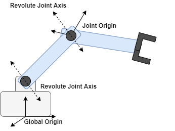
There are two main assembly features that need to be defined for every link-joint-link pair. These are:
Joint Origin (also called coordinate frame): The joint’s coordinate frame defines the position of the joint in 3D space with respect to the rest of the robot’s body. The whole robot in turn has its own origin frame (called the global origin) that tells the simulator its position with respect to the world. These are simply the standard Solidworks “coordinate frame” features.
Joint Axes: The joint’s movement is defined by the axis of the joint. For instance, revolute joints rotate around their axis while prismatic joints translate along their axis. The axis is also the standard Solidworks “axis” feature.
The 4 acceptable joint types and their assembly specifications are mentioned below. Make sure to strictly follow these assembly specifications since the SW2URDF tool relies on them to interpret the robot’s assembly.
Revolute Joint: This is a 1-DOF rotating joint. The joint origin must be a part of the child (rotating) link while the joint axis can be a part of either the parent or the child link. This joint allows for 360-degree rotation but this does not include continuous rotation (similar to that of a wheel). For continuous rotation use a continuous joint.
Continuous Joint: This is just a revolute joint that can rotate continuously. It is assembled exactly the same as a revolute joint.
Prismatic Joint: This is a 1-DOF translating joint. The joint origin must be on the assembly level. Hence, add a coordinate frame feature on the robot’s assembly and place in the middle of the translating line. The axis can be a part of either the parent or the child link
Fixed Joint: These are the simplest joints. They are usually directly included by the plugin but the general rule to add one is to include the coordinate frame on the assembly level.
N-bar linkages where the mechanism exists in a looped configuration are currently not supported.
The URDF file allows for different visual and collision models to be defined for each link. The collision model is the model whose physics actually count. These physics are used by the simulation to estimate dynamics and to interpret contacts. The general convention is to have as simple of a collision model as possible. The more complex it is, the slower your simulation works. The visual model is simply a visible layer on top of the collision model. In the simulation, the collision model is invisible. Hence, the visual model is the part that you see moving. You do not have any constraints on the complexity of the visual model since its dynamics and motion are never really calculated in the first place. The WPI-Robotics resource mentioned above has some great options on how you can reduce the complexity of the collision model.
There however is a small issue with the exporter where you can not really export both the visual and the collision geometry simultaneously. Hence, the workaround for this is to first export a package with the visual model. Then simplify the CAD, and export the package with the collision model. Finally, you can manually add the collision .stl files into the package with the visual files and simply change the paths to the collision files in the .urdf file.

For example, if your filesystem is as shown above, then for link1, the <link> element in the .urdf file might look like this.
<link
    name="link1">
    <inertial>
    </inertial>
    <visual>
      <origin
        xyz="0 0 0"
        rpy="0 0 0" />
      <geometry>
        <mesh          filename="package://myrobot_description/visual/link1_visual.STL" />
      </geometry>
      <material
        name="">
        <color
          rgba="1 1 1 1" />
      </material>
    </visual>
    <collision>
      <origin
        xyz="0 0 0"
        rpy="0 0 0" />
      <geometry>
        <mesh
 filename="package://myrobot_description/collision/link1_collision.STL" />
      </geometry>
    </collision>
  </link>
And that is basically it. The tool essentially generates a ROS package containing your urdf file, its meshes and some other files. To make it work in a ROS workspace, you will have to run catkin make.
By this point, you should have a working robot URDF file. You can test your output in RViz but I would recommend a much easier online tool linked here. Just drag and drop you whole package into the browser. BIG BIG thanks to the developer of this URDF visualizer tool (Garett Johnson, NASA JPL).
Now, the next steps are to add transmission elements and plugins to the URDF for actuation and control. These elements vary based on the simulation software and hence I will cover them in another blog. Finally, since the tool itself is kind of buggy, you might easily run into some random inconsistencies. Below are some tips that I have picked up to try to get consistent results.
Make an origin coordinate frame in the assembly as well. This is the global origin and will correspond to the location that the robot gets placed when it is imported into the simulation software.
Keep the joint axes, coordinates and joint types as “automatic selection”. First, always try using the automatic options as they usually always work. If issues arise, then follow the below-mentioned steps to try and fix the URDF file.
Set the base link’s origin as the global origin defined in the assembly (alternatively and preferably, you can also define a separate global origin as mentioned above). For prismatic joints define the linear axis just on the part that is stationary and do not define a coordinate system. The coordinate system is defined along the axis automatically. If this fails, then try setting it manually.
Note that if keeping settings to all automatic does not work then define the axes by yourself but still keep coordinate frames on automatic. Essentially, define coordinate frames on individual parts (frame to be defined on moving part not fixed part), but just select the automatic option in the SW2URDF dialogue box. The final coordinate frames will then be superimposed on the ones you defined. This works much better than manually selecting the coordinate frames.
Note that if this too does not work then try setting it to all auto and redefining the automatically created coordinate frames by manually setting the point and axis directions.
Also, note that positive Z points upwards in the world (hence the global origin must have its Z-axis pointing upwards)
Finally, as promised, here’s the non-Solidworks workaround.
Generating URDFs using MATLAB & OnShape
If you do not have access to Solidworks, then there is a sort of annoying but super functional workaround that involves using MATLAB and the OnShape online CAD tool. Here are the basic steps to get this to work.
Design your robot in OnShape (it's free!). Or else, import your current parts into OnShape as .stl or .step files and create an assembly. While creating the assembly, make sure to follow the URDF assembly guidelines mentioned above. OnShape also has a shift origin feature that you can use to change your child link origins to be according to the specific joint type.
Use the smexportonshape(‘link to CAD’) command to export your onshape CAD models into MATLAB in the URDF format. Voila! You now have an auto-generated URDF file. You might have to tweak a few things manually and create your own collision/visual geometry but this method simplifies at least 90% of all the work.
Finally, if you intend to use the URDF in Simulink, use smimport(‘assembly.xml’).
Follow this video tutorial by the MATLAB YouTube Channel for more details.
Yorumlar